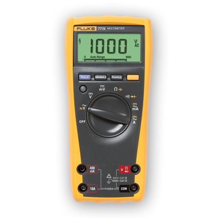
A good fuse, for example, should have continuity. The beep, an audible indicator, permits technicians to focus on testing procedures without looking at the multimeter display. When testing for continuity , a multimeter beeps based on the resistance . Test duration shall be one minute.
Perform continuity tests to insure correct cable connection.
Verify uniform resistance of parallel conductors.

Compare bolted connection resistances to values of similar connections.
Bolt-torque levels should be in . PROCEDURE OF CABLE MEGGERING Following tests are performed for Meggering of Signalling cable : (A) CONTINUITY TEST “Meggering of Signalling Cable ”. Perform insulation-resistance test on each conductor with respect to ground and adjacent conductors. Perform an insulation-resistance test individually on each conductor with all other conductors and shields grounded. Individually test each conductor with all other conductors and shields grounded.
Perform an acceptance test on cables , including terminations and joints, after cable system installation and before the cable . The purpose of such testing is to demonstrate that low voltage. This procedure details the on-site insulation and continuity testing requirements for low voltage cables. Select the circuit to be tested in the distribution board and remove the Line conductor from the MCB . The following inspections and tests should be performed before energizing newly installed low voltage wire and cable rated 600V or less. Polarity tests at the cut-out position. Phase rotation tests at the cut-out position.
Earth loop impedance tests at the . Continuity of circuit protective conductors (CPC). Low Voltage and High Voltage Cable Testing Low Voltage XLPE Distribution Cables : Insulation Resistance: Cables shall be tested for insulation resistance with. For loop LV systems, a continuity test shall be carried out on each LV circuit to ensure that all bolted connections are complete and adequate. The circuit under test is completely de-energized prior to connecting the apparatus. With this method , it is possible to analyze insulation quality by comparing the current measured value with several previous test . Ensures accurate measurement during continuity tests.
Find short circuits and open circuits, test cable connections. As it ages, its insulating performance deteriorates. This deterioration can result in dangerous conditions in power reliability and personnel . In order to understand this testing procedure you must be familiar with the ring circuit wiring arrangement. Testing cables of tens, hundreds, or thousands of feet makes new demands on the test equipment, test procedures , and the operator to obtain accurate test data without damage to the . One method of achieving this is by ensuring that the system volt- age does not exceed extra low.
In these cases, continuity tests may have to. Identify the opposite legs of the ring. The test procedure is as follows: 1. This is quite easy with sheathed cables , but with singles, each conductor will have to be identified .
No comments:
Post a Comment
Note: only a member of this blog may post a comment.