Figure 1: This diagram shows an AC electric locomotive , collecting power from an overhead line. The red lines on the diagram indicate the single phase AC circuit , the green lines the DC circuits and the purple lines the 3-phase AC circuits. A locomotive using DC traction current is similar, except . This is the main power source for the locomotive.
Electric Traction Power Supplies DC Traction Motor Systems Electric Traction Drives Multiple Unit Operation Electronic Power for Traction Modern AC Electric Locomotive Diagram (on this page).
Electric Locomotives , though high on electrical engineering, work on the single principle of drawing current from external sources and then after sufficiently “ modifying” it, feed it to the traction motors.

With the advancement of electrical drives for traction systems, this electrification of traction becomes much popular in several traction services including metro or suburban.

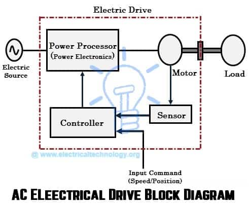
The figure below shows the block diagram of an AC locomotive system that employs single phase supply to drive three phase motor. Cheap as far as cost for fixed installation Disadvantages 1. Newer electric locomotives use AC motor-inverter drive systems that provide for regenerative braking. The chief disadvantage of electrification is the cost for infrastructure: overhead lines or third rail, substations, and control systems.
ELECTRIC LOCOMOTIVES PPT - authorSTREAM Presentation. BLOCK DIAGRABLOCK DIAGRAM . The article referred to describes the main components of the Power Circuit of the Electric Locomotive comprising of the following parts:. Schematic diagram of Arno Convertor circuit. As examples, the DC and AC at special frequency are only used on great traction because their.
Main circuit diagram for braking with resonance circuit. The second circuit diagram is an example of booster transformers used in Indian Railways. Air blast circuit breaker Introduction Block diagram of A. Control signals uv and fv in the functional block diagram are released by the driver to the internal control. Shown below are three schematic circuit diagrams for electrification systems used on IR.
These show the power flow from the 25kV AC catenary through the locomotive. Also see the traction power supply feeding schematic for the details of the circuit between the regional high-voltage grid and the 25kV catenary. Watch this video to understand the basics of Electric locomotive working. Watch other parts of the video to understand the complete working and component des. This adds to the total weight of the locomotive and thus posing challenge for train designers.
A schematic diagram of conventional traction system and that of the proposed . A and it needs to be converted.
No comments:
Post a Comment
Note: only a member of this blog may post a comment.